I really enjoy listening to (loud) music. While this is generally no problem, it sometimes prevents me from hearing the doorbell. When our last intercom system stopped working, we just bought a cheap wireless doorbell with two receivers. Both are placed in the hallways of different floors. So with the door closed, the ringing of the bell is quite damped.
As the wireless doorbell uses the 433 MHz frequency, I sniffed the signal and build my own receiver instead of buying another one. This could also be integrated with my own home automation system to e.g. let all my room lights blink when a visitor rings the bell - quite funny.
Hardware
I had laying around some window and door alarms which normally work with magnetic sensors. As they are quite loud and have a lot of space left in the enclosure, I thought they would be perfect. They also got a switch to turn the alarm on or off.

The general idea was to use a microcontroller with a pin connected to the battery terminals of the alarm. As soon as the microcontroller receives the doorbell signal via a 433 MHz receiver, it should power the buzzer. I used the ESP8266 (ESP-12F) as it’s small enough to fit inside the enclosure, added a micro USB female connector for powering it and a tactile switch for entering the download mode of the ESP. Here’s the schematic:

Note that my ESP works with 5 V instead of 3.3 V as most of them. Consider adding an step-down converter to avoid breaking your ESP. I also connected the Tx and Rx pin of the ESP to the USB connector to reprogram it later on via an FTDI. You can also add a DIY antenna to the 433 MHz receiver to get a much better range. The result it not beautiful, but it fits:
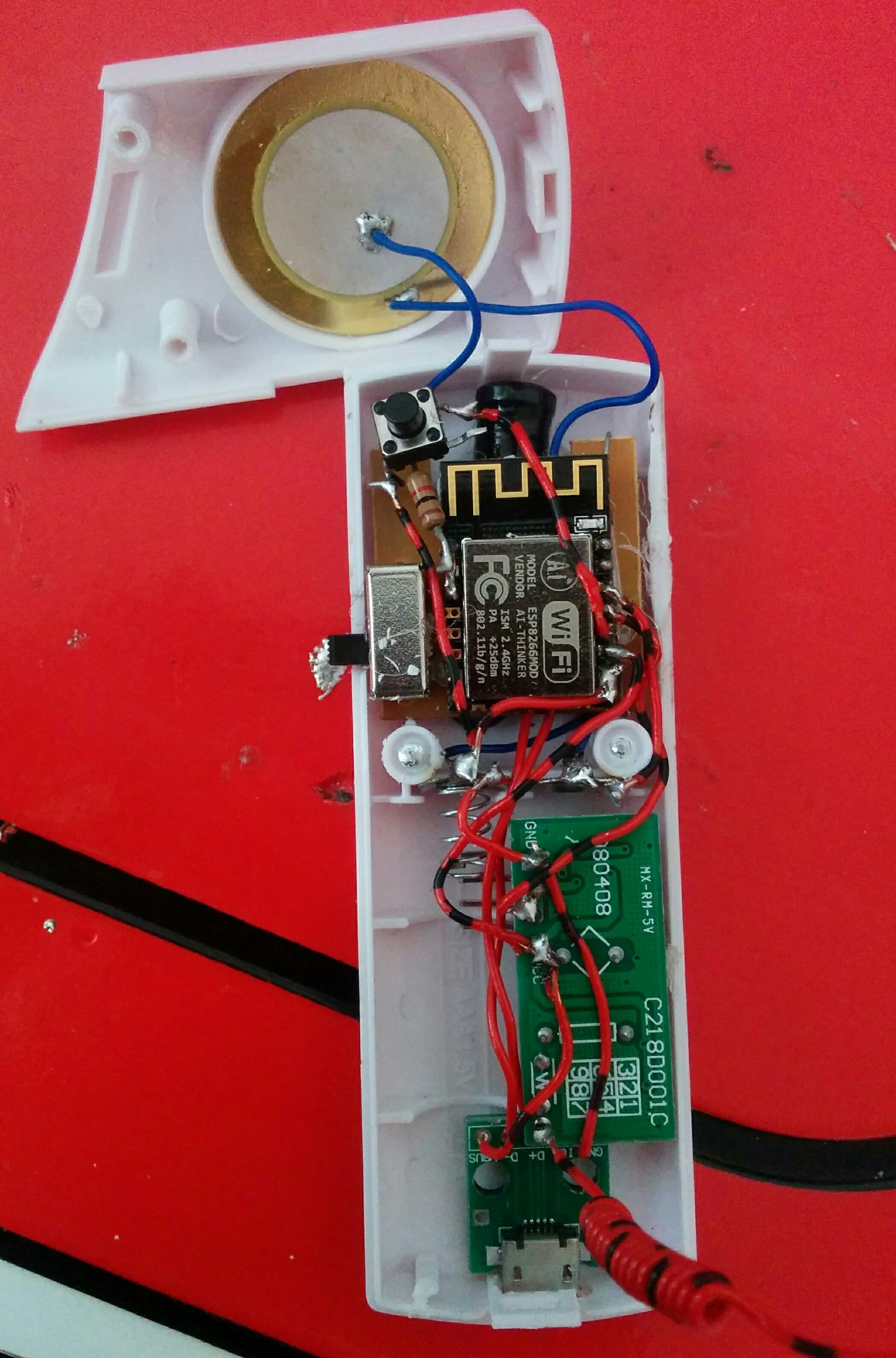
I also drilled holes on the front of the enclosure for the antenna and on the bottom for the USB connector.
Software
For receiving the 433 MHz signals, I used the rc-switch library. It also works with the ESP when using the Arduino framework. You can easily install the library via the Arduino IDE and the ESP board via the board manager. Then I just ran the example receive sketch and pushed the doorbell a few times.
This way I got the value and the protocol to filter for the doorbell signal as I don’t want to catch all the 433 MHz signals of my neighborhood. You can also use this information together with the delay to send the doorbell signal (just modify the send demo sketch) to let all the receivers in the house ring - that’s the nerd way of a knock-a-door-run. Of course you can also use this for useful applications like adding a second sender with a custom button.
In the end, I modified the example receive sketch a bit, to switch on the buzzer for five seconds via pin 5 as soon as I receive the 433 MHz signal with the determined value and protocol:
#include <RCSwitch.h>
#include <ESP8266WiFi.h>

RCSwitch recv = RCSwitch();
unsigned long enabled = 0;

void setup() {
  WiFi.mode(WIFI_OFF);

  pinMode(4, INPUT_PULLUP);
  pinMode(5, OUTPUT);

  recv.enableReceive(digitalPinToInterrupt(4));
}

void loop() {
  if (recv.available()) {
    if (recv.getReceivedValue() == 14290673 && recv.getReceivedProtocol() == 1) {
      digitalWrite(5, HIGH);
      enabled = millis();
    }

    recv.resetAvailable();
  }

  if ((enabled != 0) && (millis() > (enabled + 5000))) {
    digitalWrite(5, LOW);
    enabled = 0;
  }
}
As mentioned before, possible extensions could use the WiFi to notify e.g. your OpenHAB system to control any of the smart home devices when someone rings. And there are many more things you could do instead.
Result
With the enclosure shut, the project looks a lot nicer:
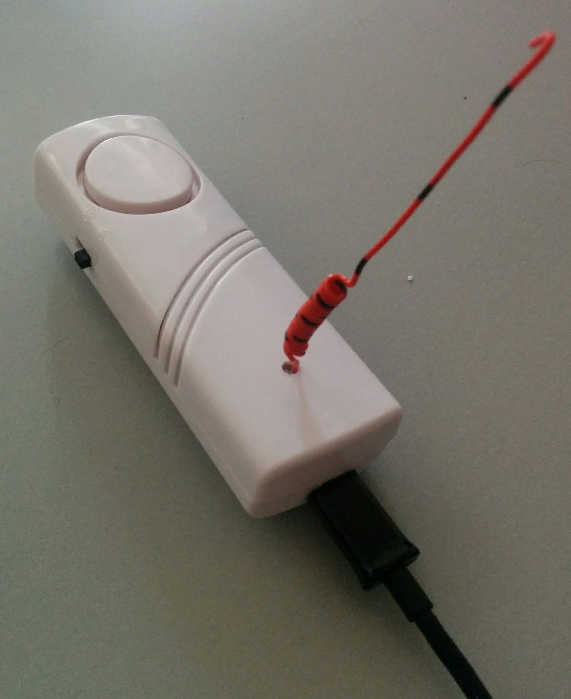
The range in my tests were quite good. It still worked through multiple walls over multiple floors. And with the button you’re still able to e.g. switch of the alarm in the night.
As a next step, I will add a MQTT client to send a message about a visitor to OpenHAB. For this, I will just reuse the MQTT part of the firmware described in this post.
Comments