As a software developer, I’m also very interested in electronics and the programming of microcontrollers. Of course I also had a look into the current hype of home automation.
What I found was rather disappointing. No real architecture standards, every manufacturer is doing its own thing. Different devices are not really working together - that’s not what the “Internet Of Things” should look like to me. Apart from that, I found the devices on the market are way to expensive for what they actually do.
To save some money while having more flexibility, I decided to start automating some of my electronic devices on my own. As I played around with the WiFi-powered ESP8266 shortly before, I used this chip as a base for my own smart things.
As I was looking around my room, I set the following goals for my project:
- Control TV and sound system
- Switch very cheap wireless sockets (lamps and other devices)
- Motion detection
- Temperature and humidity sensors
- Determine window/door states
All the devices should be controlled by an ESP in my room, which is connected to my WiFi network. I also wanted a centralized configuration for all (in future added) ESPs and Over-The-Air firmware updates via WiFi and an own update server.
As a little motivation, the parts list:
| Part | Price $ |
|---|---|
| ESP8266 ESP-12F | 1x $1.75 |
| DHT11 (temperature & humidity) | 1x $1.26 |
| 433MHz Transmitter (wireless sockets) | 1x $0.62 |
| 433MHz Antenna (or build yourself) | 1x $0.20 |
| microUSB Connector | 1x $0.11 |
| Motion Sensor | 1x $0.78 |
| Pushbutton | 1x $0.01 |
| Magnetic Contact (windows/doors, ..) | 1x $0.60 |
| IR LED (for TV, sound system, ..) | 1x $0.05 |
| 1k Resistors | 3x $0.01 |
| Wireless Socket (433 MHz) | 1x $5.00 |
| Total | $9.41 |
You may already have laying around some of the parts or can salvage them from old stuff. I ordered most of them from AliExpress, where I also got the prices of the parts list from. For programming the ESP you also need an FTDI for less than $2.
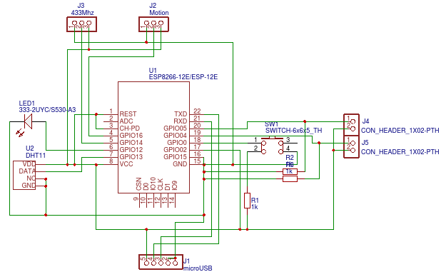
After some breadboard prototyping I layed out a schematic in EasyEDA and created my first PCB ever (don’t blame me for using autorouter). You can find the layout and the PCB here. If you wonder why I’m running my ESP with 5V instead of the recommended 3.3V: My ESPs were much more stable while running them with 5V and there are definitely much more things that can be improved in my schematic.
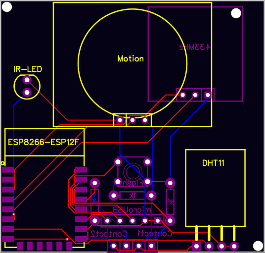
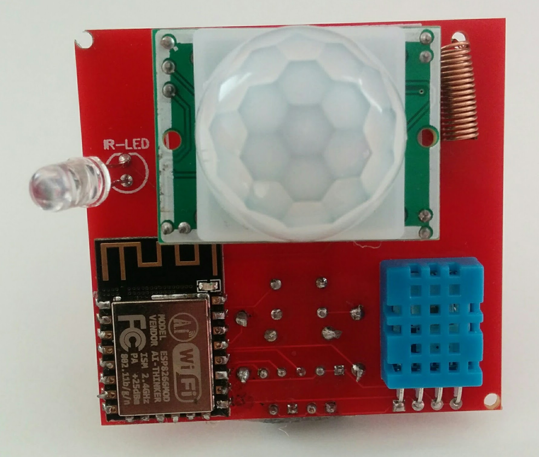
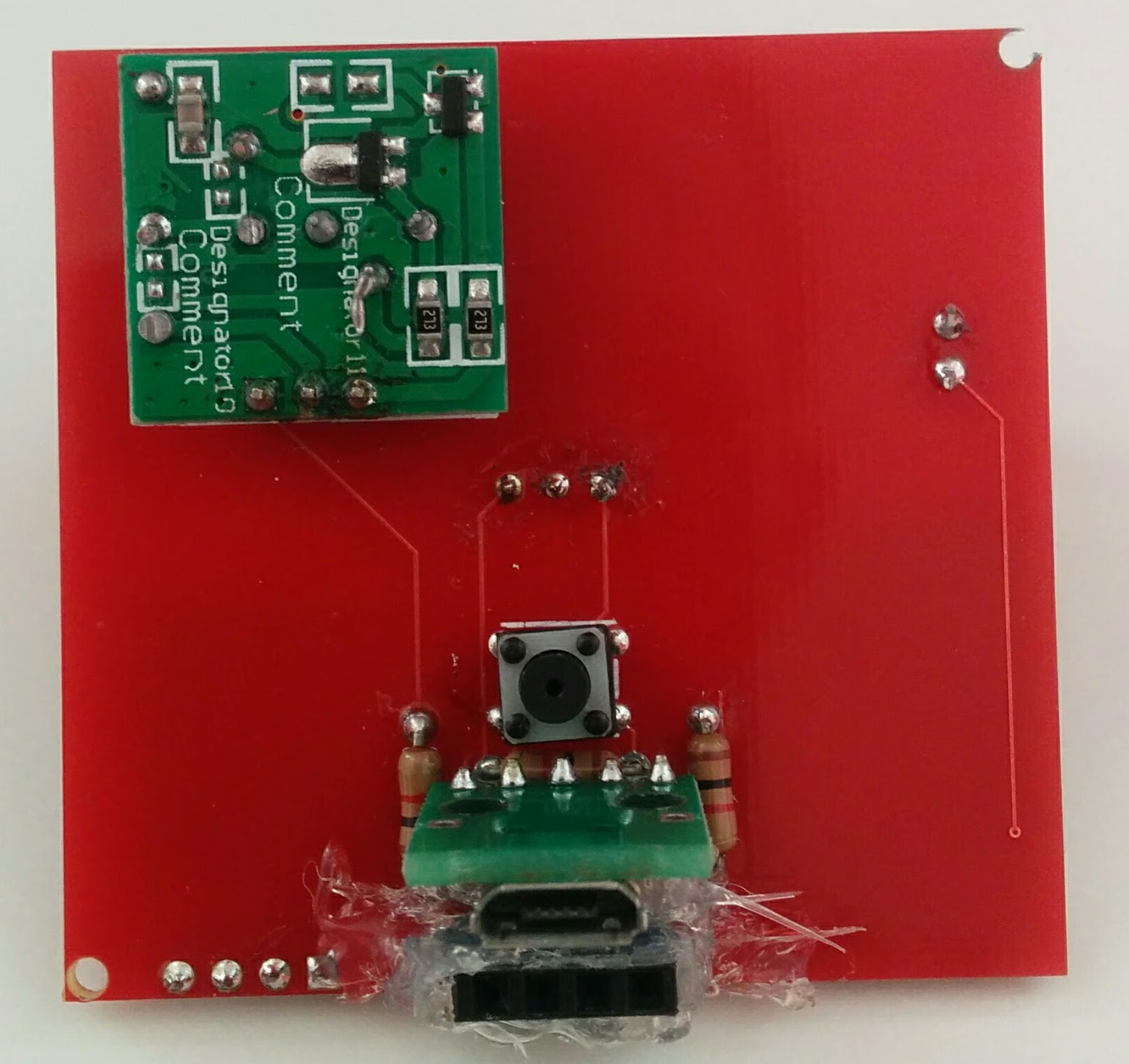
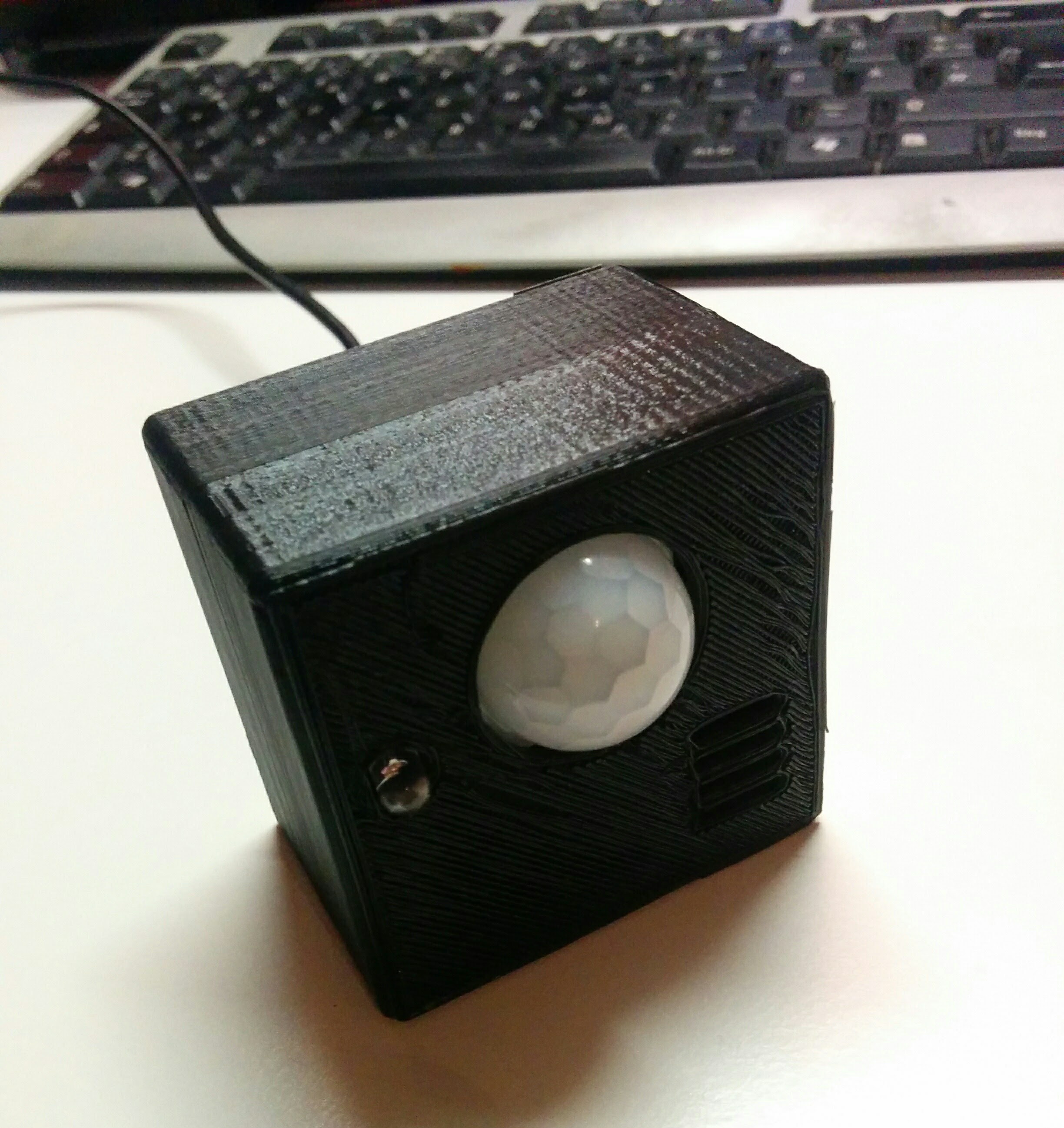
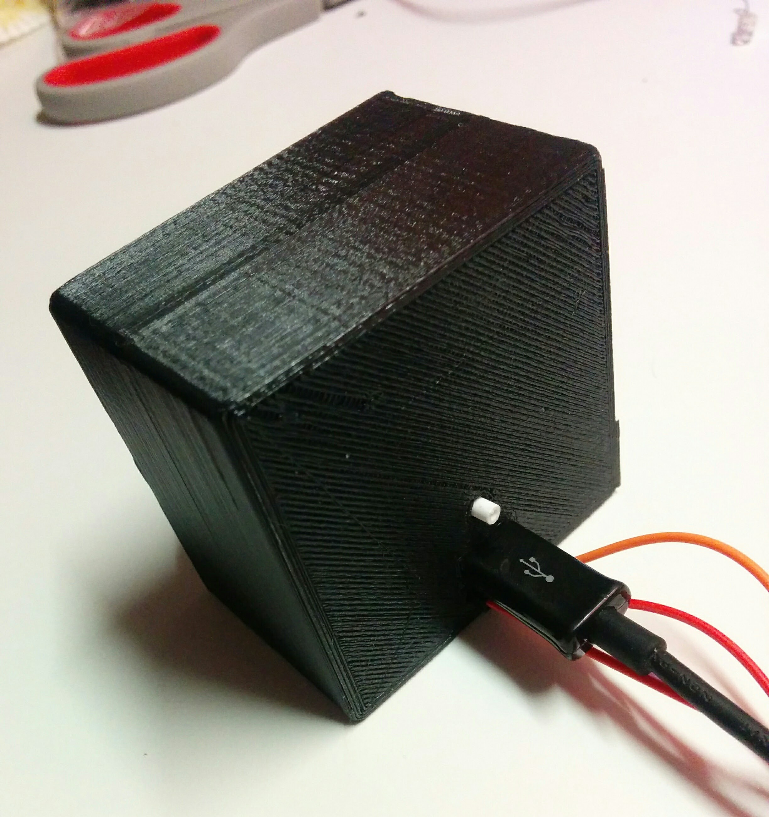
Although the holes are too close to the edges of the PCB and the resistor underneath the pushbutton is a bit too close to the microUSB port, the PCB came out pretty well for my first try. I ordered 5 pieces of the PCB at Elecrow for less than $10. After soldering, I also created a little box for my project and printed it out with a 3D-printer of a friend.
As running costs are also very interesting: The hardware used about 0,41W in my measurements. This results in around 1 € per year with average costs of 0.28 €/kWh for electricity in Germany.
The firmware itself is using MQTT for communication. This allows easy and lightweight interfacing with various clients. You can find the source code on my GitHub (excuse my bad C/C++ skills). In my overall solution I communicate with the ESPs via OpenHAB 2.
More details on the source code as well as the overall architecture of the project and OpenHAB will follow in future posts.
Comments